About PN JUNCTION DIODE CHARACTERISTICS
Specification:
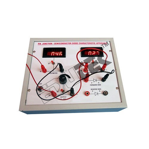
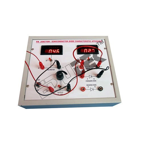
PN JUNCTION DIODE CHARACTERISTICS
Input: 230 Volts AC 50Hz DC Output
Power supply: 0-2 V DC for forward Bias
Power supply: 0-30VDC for reverse Bias
Provided with two Digital meters
Comprehensive Experimentation KitThis PN Junction Diode Characteristics unit comes as a complete table-top instrument to facilitate undergraduate and postgraduate electronics experiments. Its modular design, fitted meters, and easy-to-use connectivity terminals simplify V-I characteristic plotting in both forward and reverse bias. Students can gain hands-on understanding of diode behavior, reinforcing theoretical concepts practically.
Reliable and Accurate MeasurementsFactory-calibrated analog meters with fine resolution (0.01V, 1mA) ensure precise voltage and current readings across the diode. Overload protection on the supply and high-grade construction promote user safety and instrument durability, supporting frequent laboratory use.
User-Friendly and Safe DesignThe unit features a robust wooden or ABS enclosure, providing a shock-proof build ideal for academic settings. Safety measures and adherence to ISI/ISO standards make it a dependable choice for both students and instructors. The setup is intuitive with included manual and banana terminal connectivity, simplifying experiments.
FAQ's of PN JUNCTION DIODE CHARACTERISTICS:
Q: How does this kit help in understanding the V-I characteristics of a PN junction diode?
A: The kit enables users to measure and plot the volt-ampere (V-I) characteristics of a silicon PN junction diode in both forward (up to 1V, 100mA) and reverse (up to 30V, leakage current measured) bias conditions. This hands-on experiment enhances understanding of diode operation, cut-in voltage, and leakage currents, reinforcing classroom theory with practical experience.
Q: What types of measurements can I perform using this diode characteristics unit?
A: You can perform forward bias measurements (voltage up to 1V, current up to 100mA) and reverse bias measurements (voltage up to 30V, monitoring leakage current) on a standard silicon PN-junction diode. The analog meters provide real-time readings for voltage and current across the diode.
Q: When should the measurement process be carried out to ensure accurate results?
A: It is recommended to perform measurements at an operating temperature between 0C and 50C, as specified, and to allow the unit to stabilize after powering up. Avoid rapid changes in voltage settings for optimal accuracy.
Q: Where is this instrument best utilized?
A: This equipment is ideally suited for engineering electronics laboratories in educational institutes. Its robust build and compliance with ISI/ISO standards make it appropriate for use by students during practical sessions and research experiments.
Q: What process should be followed to connect and use the experiment unit safely?
A: Connect the PN junction diode and meters using the provided banana leads, set the required DC voltage through the control knob, and monitor current and voltage on the analog displays. Always ensure connections are secure and the supply does not exceed the rated voltage and current limits. Detailed operating instructions are provided in the included manual.
Q: How does overload protection benefit users?
A: Overload protection on the supply ensures that the instrument, connected diode, and users remain safe in case of accidental excessive voltage or current. This safeguards both the experiment and the equipment against damage and electrical hazards.







 Send Inquiry

 Send Inquiry


