


Electrical Connection Of Refrigerant Compressors
Product Details:
X
Product Description
ELECTRICAL CONNECTION OF REFRIGERANT COMPRESSORS
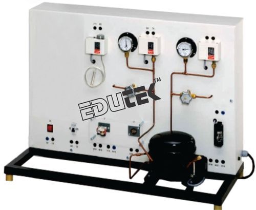
The wiring of electrical components for the start and operation of refrigerant compressors is a typical task in the field of refrigeration. Safety aspects also play an important role. With this knowledge and these skills can be acquired. All components are operated and tested with mains voltage to provide high relevance for practice.
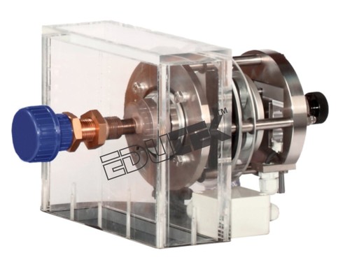
The electrical components for the start and operation of the refrigerant compressor are arranged clearly visible. The electrical connection of the individual components is made with cables via the lab jacks. The components are e.g. the capacitor and start-up relay necessary to start the motor. The circuit diagram on the front panel enables the easy allocation of the individual components.
The refrigeration circuit with compressor and receiver enables the checking of the pressure switches on the intake and delivery side of the compressor. The pressure is set via valves and the pressure switch tripped. Two manometers enable the monitoring of the pressure curve. If one of the pressure switches trips, the current supply to the compressor is interrupted. The wiring and checking of other typical components of the safety chain, e.g. circuit breaker and automatic fuse, is also carried out.
The well-structured instructional material sets out the fundamentals and provides a step-by-step guide through the experiments.
The unit shall perform the following experiments and investigations:
Learning Objectives / Experiments
- Read, understand, wire and test electric circuit
- Diagrams for refrigerant compressors
- Design and operation of electrical components of
- Refrigerant compressors
- Start-up capacitor
- Start-up relay
- Overheat protection
- Automatic fuse
- Pressure switch
- Thermostat
- Design and testing of a safety chain
- Representation methods in electrical engineering
- Symbols
- Circuit diagrams
- Safety aspects when handling mains voltage
Specification
- Experimental unit from the practical series for the training of mechatronics engineers for refrigeration
- Correct electrical connection of a refrigerant compressor
- Refrigerant circuit with compressor, receiver, 2 valves and 2 manometers to investigate pressure switches on the delivery and intake sides
- Electrical components for the start and operation of the compressor mounted clearly visible
- Lab jacks and cables to connect the electrical components
- Operation of a thermostat
- Circuit diagram on the front panel for easy identification of the components
- Refrigerant R134a, CFC-free
Technical Data
- Refrigerant compressor
- Power consumption: approx. 165W
- Receiver: 0,8L
- Manometer measuring ranges
- Delivery side: -1...24bar
- Intake side: -1...9bar
- Pressure switch control range
- Delivery side: 8...32bar
- Intake side: -0,9...7bar
- Thermostat: -5...35°C
- Electrical components for the compressor
- Start-up capacitor
- Start-up relay
- Overheat protection (bimetallic)
- Automatic fuse
Dimensions and Weight
- LxWxH: 920x410x660mm
- Weight: approx. 45kg
Enter Buying Requirement Details
Other Products in 'Fluid Mechanics Lab Equipment' category
"We deal all over World but our main domestic market is South India"

- EDUTEK INSTRUMENTATION
None - Factory: 70, Edutek House, Main Road Vikaspuri, Industrial Area, Ambala Cantt - 133006, Haryana, India
- Phone :91-171-2699855

- Email Id : edutekgroup@gmail.com
- Mr Aditya Kumar (Director-International Sales)
- Mobile :+919996644855, +918930444855
- edutekgroup@gmail.com
 |
EDUTEK INSTRUMENTATION
All Rights Reserved.(Terms of Use) Developed and Managed by Infocom Network Private Limited. |