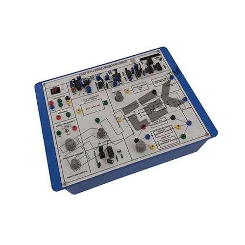
About PHASE LOCKED LOOP
Specification:
PHASE LOCKED LOOP
Study of PLL
A.F. Generator 0-10KHz Variable Amplitude of 5Vp-p
On Board Modulating Signal Oscillator 0-10KHz
Carrier generator Using 8038 IC 1-10KHz
Power Supply:
Fixed DC Power Supplies +12V DC, 250mA
Fixed DC Power Supplies +5V DC, 250mA Operated on Mains power 230V, 50Hz +10%
Components are mounted on the panels:
IC
Capacitors
Resistors
Diode
Precision and Versatility for Learning and ExperimentationDesigned with engineering electronics in mind, this PLL instrument merges classroom theory with hands-on experience. Its variable controls for both frequency and phase allow users to produce and manipulate synthesized output signals tailored to a variety of experiments. The durable PCB, test points, and banana terminals ensure reliable performance, whether for demonstrations or advanced projects.
User-Friendly, Safe, and Compatible DesignThe module's standard breadboard-compatible dimensions (130mm x 105mm x 30mm) and accessible interface with DIP sockets simplify integration into existing setups. With fuse-based polarity protection and a 12V DC supply, safety and device preservation are paramount. Full documentation and included accessories enable immediate and code-free experimentation.
FAQ's of PHASE LOCKED LOOP:
Q: How do I connect and set up the Phase Locked Loop module for my experiments?
A: To set up the PLL module, connect your external 12V DC adapter to the input, use the banana terminals for waveform signal input and output, and refer to the user manual for adjusting the frequency and phase controls. Patch cords and clear instructions are included to streamline the process.
Q: What are the advantages of using this PLL module in engineering electronics laboratories?
A: This PLL instrument provides hands-on experience in phase lock and frequency synthesis phenomena. It enables students and technicians to visualize and experiment with real-time frequency and phase adjustments, enhancing understanding and skill development in electronic communications and controls.
Q: When is it necessary to use the variable frequency and phase controls?
A: Variable frequency and phase controls are essential when simulating or demonstrating signal synchronization, demodulation, or precise frequency tracking scenarios in engineering electronics experiments, particularly when tailored outputs or test conditions are required.
Q: Where is this Phase Locked Loop most effectively used?
A: This module is ideal for use in academic electronics labs, research institutions, and training centers where phase synchronization, frequency synthesis, or waveform analysis are part of the curriculum or research focus.
Q: What process should I follow if the module does not power on?
A: If the module does not power on, first check the 12V DC adapter connection and verify the integrity of the fuse on the input, which provides polarity protection. Ensure that all connectors are properly inserted, and consult the troubleshooting section of the instruction manual.
Q: How does the polarity protection work in this device?
A: Polarity protection is provided via a fuse on the input power line. In case of reverse voltage connection, the fuse prevents current from reaching the device, protecting internal components from damage.
Q: What are the main benefits of this PLL module over conventional setups?
A: This module's robust construction, instant electronic response, breadboard-compatible dimensions, and inclusion of accessories allow for convenient use, safe operation, and reliable demonstration of PLL principles, making it superior for teaching, testing, and experimental validation.


 Send Inquiry
 Send Inquiry
