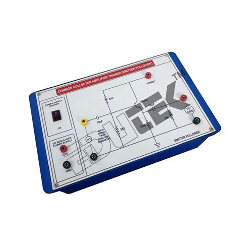
About COMMON COLLECTOR AMPLIFIER
Specification:
COMMON COLLECTOR AMPLIFIER
Features:
Front panel built with high class insulated Printed Circuit Board sheet with well printed circuits and symbols.
Fuse for Short Circuit protection
Instruction manual.
Connections are brought out through 4mm Colored Sockets.
Patch Cords 4mm.
The trainer is housed in ABS Plastic cabinet.
Size of the trainer set 12x8
Easy Integration and DemonstrationThis emitter follower amplifier offers straightforward assembly, either ready-to-use or semi-assembled, and is compatible with breadboards for rapid experimental setups. Its convenient connector options, including screw terminals and pin headers, simplify wiring, making it accessible for students and engineers alike.
Reliable and Durable Engineering SolutionManufactured on sturdy FR4 epoxy glass PCBs with standard electronic component coloration, the amplifier withstands regular handling and exhibits reliable performance up to 100 kHz, making it well-suited for educational labs and demonstration instruments in electronics engineering contexts.
Optimal Performance for Audio and Signal ProcessingWith high input impedance and low output impedance, this amplifier is optimal for buffering low-level analog signals without significant voltage gain. It ensures strong current driving capability, making it ideal for interfacing between signal sources and subsequent circuit stages in test and measurement instruments.
FAQ's of COMMON COLLECTOR AMPLIFIER:
Q: How does a common collector amplifier work in this product?
A: The common collector amplifier, also known as an emitter follower, operates by amplifying the input signal's current while maintaining a voltage gain slightly less than one. It provides high input impedance and low output impedance, making it excellent for buffering and impedance matching between circuit stages.
Q: What are the primary benefits of using this amplifier module?
A: The amplifier offers high current gain and superior buffering, allowing effective signal transmission without significant voltage loss. Its compact design, robust PCB, and ready-to-use assembly simplify demonstration and integration in engineering educational setups.
Q: When should I use this module in my engineering projects?
A: This module is especially beneficial when you need to interface a signal source with a high impedance to a load with low impedance, such as in audio processing, laboratory experiments, or for testing and measurement tasks requiring signal buffering.
Q: Where can I connect the inputs and outputs on the PCB?
A: The module provides dedicated screw terminals or male header pins for easy connection of input signals, outputs, and DC supply. Labeled test points allow for quick verification and monitoring during assembly, demonstration, or troubleshooting.
Q: What is the assembly or installation process for this amplifier?
A: Depending on the chosen option, the module comes either fully assembled or semi-assembled. Simply connect your input signal, output load, and 9V DC power supply to the appropriate connectors or terminals, and verify connections using the provided test points.
Q: How is reverse polarity protection implemented in this module?
A: If provided, reverse polarity protection typically involves a diode or similar component, safeguarding the circuit against accidental reversal of the DC supply input, ensuring the module's durability and operational safety.
Q: What types of signals and power supplies are supported by this amplifier?
A: The amplifier is designed to handle low-level analog signals-such as audio signals or test waveforms-powered by an external 9V battery or DC adapter, making it adaptable for various practical engineering electronics experiments.


 Send Inquiry
 Send Inquiry
