


Electrical Faults In Refrigerant Compressors
Product Details:
X
Product Description
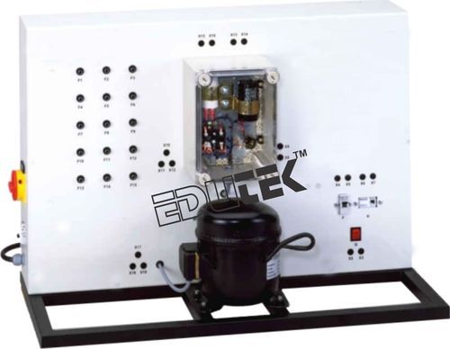
ELECTRICAL FAULTS IN REFRIGERANT COMPRESSORS
Identifying electrical faults in refrigeration systems requires comprehensive knowledge This knowledge includes the design and operation of the individual electrical components as well as the reading of circuit diagrams. The electrical components for the start and operation of a refrigerant compressor are clearly visibly arranged in a transparent showcase and already wired. The capacitor and start-up relay required for the motor are examined. Typical protection devices, such as circuit breaker and automatic fuse, are also arranged clearly visible.
The simulation of 15 different faults, e.g. coil fracture in the motor, short circuit in the operating capacitor or welded contacts in the start-up relay, is possible. For fault indication, voltages and resistances are checked at the lab jacks with the multimeter. The depiction of the circuit diagram on the front panel facilitates the allocation of the measuring points. The well-structured instructional material sets out the fundamentals and provides a step-by-step guide through the experiments.
Learning Objectives / Experiments
- Electrical connection of refrigerant compressors
- Read and understand electrical circuit diagrams
- Design and operation of the electrical components of a refrigerant compressor
- Start-up capacitor
- Start-up relay
- Operating capacitor
- Overheat protection
- Main contactor
- Automatic fuse
- Fault finding in electrical components in idle state
- Under mains voltage
Specification
- Experimental unit from the practical series for the training of mechatronics engineers for refrigeration
- Investigation of the electrical components for the operation of a refrigerant compressor
- Real refrigerant compressor from practice
- Electrical components for the start and operation of the compressor arranged in the transparent switch cabinet
- General safety devices mounted clearly visible
- Circuit diagram depicted on the front panel
- Identification of 15 faults: multimeter measures voltages or resistances at the lab jacks
Technical Data
- Refrigerant compressor
- Power consumption: approx. 870W
- Electrical components for the compressor
- Start-up capacitor
- Start-up relay
- Operating capacitor
- Overheat protection (bimetallic)
- General safety devices
- Main contactor
- Automatic fuse
Dimensions and Weight
- LxWxH: 900x400x650mm
- Weight: approx. 60kg
Enter Buying Requirement Details
Other Products in 'Fluid Mechanics Lab Equipment' category

"We deal all over World but our main domestic market is South India"

- EDUTEK INSTRUMENTATION
None - Factory: 70, Edutek House, Main Road Vikaspuri, Industrial Area, Ambala Cantt - 133006, Haryana, India
- Phone :91-171-2699855

- Email Id : edutekgroup@gmail.com
- Mr Aditya Kumar (Director-International Sales)
- Mobile :+919996644855, +918930444855
- edutekgroup@gmail.com
 |
EDUTEK INSTRUMENTATION
All Rights Reserved.(Terms of Use) Developed and Managed by Infocom Network Private Limited. |