


Electrical Faults In Full Air Conditioning Systems
Product Details:
X
Product Description
ELECTRICAL FAULTS IN FULL AIR CONDITIONING SYSTEMS
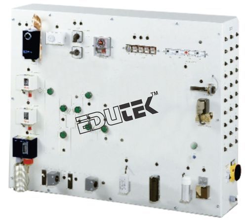
Electrical faults in air conditioning systems requires comprehensive knowledge. This knowledge includes the design and operation of the individual electrical components as well as the reading of circuit diagrams. helps to acquire this knowledge. demonstrates the electrical circuit of a complex full conditioning system with heat pump function. The control circuits are actually present. The components in the load circuits are simulated (e.g. compressor, heater, 4-way reversing valve).
With low air humidity the hygrostat activates the humidifying function. Typical protection devices, such as circuit breaker and frost protection monitor, complete the electrical circuit. The operating state of the simulated components is indicated via lamps in the circuit diagram on the front panel. The simulation of 30 different faults, such as coil fracture in the motor or faulty relays, is possible. For fault identification the voltages or resistances at the lab jacks are checked with the multimeter. The depiction of the circuit diagram on the front panel facilitates the allocation of the measuring points.
The well-structured instructional material sets out the fundamentals and provides a step-by-step guide through the experiments.
The unit shall perform the following experiments and investigations:
Learning Objectives / Experiments
- Electrical design and operation of full conditioning systems
- Reading and understanding electrical circuit diagrams
- Design and operation of electrical components in an air conditioning system
- Start-up capacitor
- Start-up relay
- Operating capacitor
- Overheat protection
- Heinemann circuit breaker
- Solenoid valve
- Defrost timer
- Float switch thermostat hygrostat
- Frost protection monitor
- Fault finding in electrical components
- In idle state
- under mains voltage
Specification
- Experimental unit from the practical series for the training of mechatronics engineers for refrigeration
- Simulation of the electrical circuit of a complex conditioning system with humidifier and heat pump function for heating, cooling and humidifying
- Real control circuits with electrical components, simulated load circuits
- Electrical simulation of compressor, 2 fans (room air, outer air), 4-way reversing valve, auxiliary heating
- Humidifier with hygrostat, solenoid valve and float switch (pump simulated)
- Hot gas defrosting by switching the 4-way reversing valve
- Operating states of the simulated components indicated via lamps in the circuit diagram
- Circuit diagram depicted on the front panel
- Identification of 30 faults: multimeter measures voltages or resistances at the lab jacks
Technical Data
- Thermostat to switch between heating/cooling
- Measuring range: 1...60°C
- Electrical compressor components
- Start-up relay
- Start-up capacitor
- Operating capacitor
- Overheat protection
- 2 pressure switches
- Electrical components of room air fan
- Start-up capacitor
- Heinemann circuit breaker
- Humidifier components
- Hygrostat: measuring range 30...100% r.h.
- Float switch
- Solenoid valve
- Heinemann circuit breaker
- Defrosting components
- Frost protection monitor: -10...12°C
- Timer: switching time 10...60min
- Circuit breaker for auxiliary heating
Dimensions and Weight
- LxWxH: 1.050x400x860mm
- Weight: approx. 48kg
Enter Buying Requirement Details
Other Products in 'Fluid Mechanics Lab Equipment' category
"We deal all over World but our main domestic market is South India"

- EDUTEK INSTRUMENTATION
None - Factory: 70, Edutek House, Main Road Vikaspuri, Industrial Area, Ambala Cantt - 133006, Haryana, India
- Phone :91-171-2699855

- Email Id : edutekgroup@gmail.com
- Mr Aditya Kumar (Director-International Sales)
- Mobile :+919996644855, +918930444855
- edutekgroup@gmail.com
 |
EDUTEK INSTRUMENTATION
All Rights Reserved.(Terms of Use) Developed and Managed by Infocom Network Private Limited. |