About OP-AMP (INVERTING/NON-INVERTING/DIFFERENTIATOR)
Specification:
OP-AMP (INVERTING/NON-INVERTING/DIFFERENTIATOR)
Front panel built with high class insulated Printed Circuit Board sheet with well printed circuits and symbols.
Fuse for Short Circuit protection
Instruction manual.
Connections are brought out through 2mm Colored Sockets.
Patch Cords 2mm.
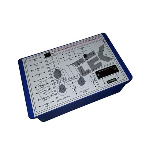
Versatile OP-AMP Training ModuleThis module allows users to configure the 741 Op-Amp as an inverting, non-inverting, or differentiator circuit. It is engineered for seamless use in laboratory and educational settings, offering students and professionals hands-on experience with analog signal processing. The multiple test points and onboard fuse protection add to its reliability and practical utility.
Durable Build and Flexible InterfaceConstructed on a sturdy FR4 epoxy PCB, the module is both durable and compact for repeated lab use. With standard 4 mm banana sockets and binding posts, it ensures quick connectivity for input, output, and feedback lines. The desktop format is breadboard compatible, enabling effortless integration with other test and measurement setups.
FAQ's of OP-AMP (INVERTING/NON-INVERTING/DIFFERENTIATOR):
Q: How do I configure the OP-AMP module for inverting or non-inverting operation?
A: You can set the module as inverting or non-inverting by connecting the input signal and feedback using the appropriate terminals and test points. The onboard layout and user manual provide guidance for changing between these configurations using banana plugs and binding posts.
Q: What are the main benefits of using this OP-AMP module in educational laboratories?
A: This module is tailored for instructional purposes, featuring clearly marked test points for input, output, and feedback, on-board fuses for protection, and easy mode switching. Students gain direct, practical insight into analog electronics operations and circuit responses.
Q: What protection features are included in the OP-AMP module?
A: The module incorporates onboard fuses to guard against over-voltage, enhancing safety during experimentation and reducing the risk of damaging components or instruments.
Q: Where can the OP-AMP circuit be used and in what applications?
A: It is optimized for use in engineering electronics laboratories, making it perfect for demonstrations, practical coursework, and hands-on experiments involving analog signal processing in educational institutions.
Q: What is the maximum supply voltage and how should the module be powered?
A: The unit supports a dual 9V DC supply or a single supply up to 18V (DC adapter or laboratory power supply). The typical supply voltage is 9V DC, ensuring compatibility with standard lab sources.
Q: How does the module facilitate practical circuit analysis and testing?
A: Multiple onboard test points are provided for easy measurement of input, output, and feedback signals, allowing users to analyze the real-time behavior of various OP-AMP configurations.


 Send Inquiry
 Send Inquiry
