About MULTIVIBRATOR (ASTABLE/ MONOSTABLE) USING OP AMP
Specification:
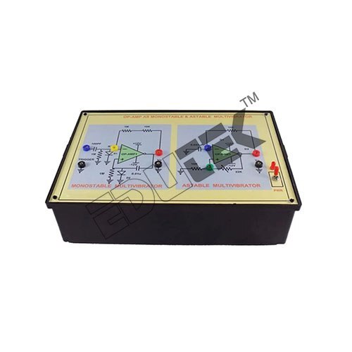
MULTIVIBRATOR (ASTABLE/ MONOSTABLE) USING OP AMP
On board circuit to study op-amp as monostable Multivibrator
On board circuit to study op-amp as astable Multivibrator.
ON/OFF switch and LED for power indication.
Bare board Tested Glass Epoxy SMOBC PCB is used.
Block Description Screen printed on glassy epoxy PCB
All interconnections are made using 2mm banana Patch cords
Versatile Multivibrator Training KitThis trainer enables students and engineers to configure and analyze both astable (oscillating) and monostable (one-shot) multivibrator circuits using an operational amplifier. Whether it's generating square waves or precise timed pulses, the kit provides hands-on learning with real, adjustable component values. Access to key circuit nodes through test pins and discrete output via LED makes it ideal for interactive demonstrations and practical experimentations.
Robust Design and Safety FeaturesBuilt with high-quality FR4 Glass Epoxy PCB material and featuring reverse polarity protection, this kit offers enhanced durability and reliable operation. An ergonomic table-top design ensures stability during use, while the included schematic simplifies assembly and troubleshooting. Protective foam-packed packaging prevents damage during transit, supporting trouble-free delivery for labs or classrooms.
Adjustable and User-Friendly OperationUsers can fine-tune frequency and pulse width through simple RC component adjustments, tailoring the kit to a wide range of experiments. Manual mode selection and triggering with tactile switches make it accessible for varied exercises in electronics studies. LED output indication ensures instant feedback, making parameter effects visible and comprehensible for learners.
FAQ's of MULTIVIBRATOR (ASTABLE/ MONOSTABLE) USING OP AMP:
Q: How do I switch between astable and monostable modes on this multivibrator kit?
A: Mode selection is achieved using the provided manual switches on the kit. For astable (oscillation) mode, you simply configure the circuit as per the included schematic; for monostable (one-shot) operation, use the designated tactile push button to provide a trigger pulse.
Q: What educational benefits does this kit provide for engineering electronics students?
A: The kit offers hands-on experimentation with multivibrator circuits, allowing students to observe waveform outputs, adjust RC components to see real-time effects on timing, and access test points for in-depth study. It supports fundamental and advanced learning in circuit design, testing, and troubleshooting.
Q: When should I use the test pins provided on the PCB?
A: Use the test pins when you wish to measure voltages, analyze circuit responses, or connect external equipment (like an oscilloscope or multimeter) at critical nodes. This feature is particularly beneficial during laboratory experiments or when verifying circuit behavior.
Q: What process should I follow to adjust the frequency and pulse width?
A: To modify frequency or pulse width, alter the resistors and/or capacitors connected in the timing sections of the circuit. The included schematic guides you in identifying these components. Changing the RC values allows you to tailor output from the low Hz to high kHz range as per experimental requirements.
Q: Where is this kit typically used, and what applications does it support?
A: Designed for educational use in engineering colleges and electronics training institutes, this kit supports lab experiments on waveform generation, pulse circuits, and timing analysis. It's also suitable for research, demonstrations, and basic prototyping in electronics engineering.
Q: What type of load can the kit's output drive?
A: The output can reliably source up to 20mA, allowing it to drive common LEDs and buzzers directly. For heavier loads, use an external driver circuit as detailed in the supplied schematic.
Q: How is the kit powered and is the power supply included?
A: The kit is powered using an external 12V DC regulated adapter. Ensure proper polarity; the onboard reverse polarity diode helps protect the circuit. The power adapter is not included and needs to be acquired separately.






 Send Inquiry

 Send Inquiry


