About FLUIDIZED BED HEAT TRANSFER UNIT
Specification:
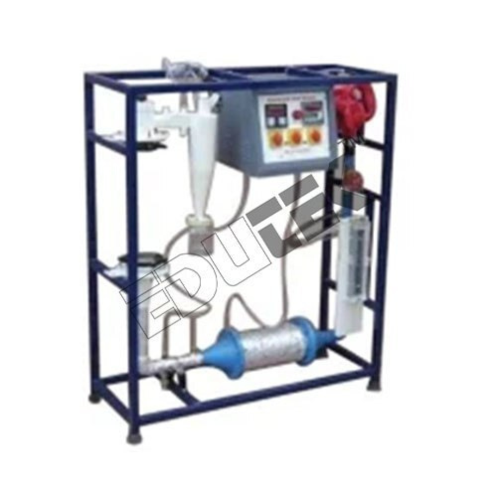
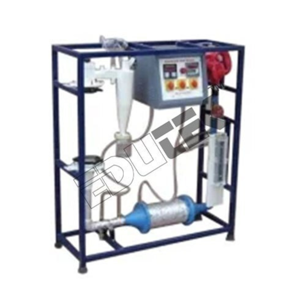
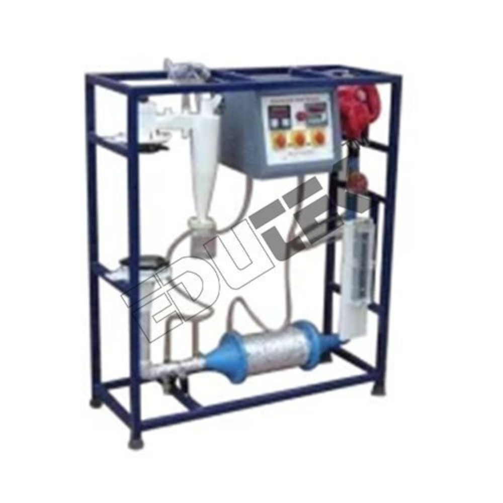
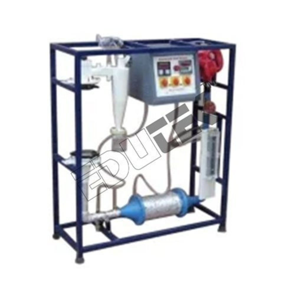
FLUIDIZEDBED HEAT TRANSFER UNIT
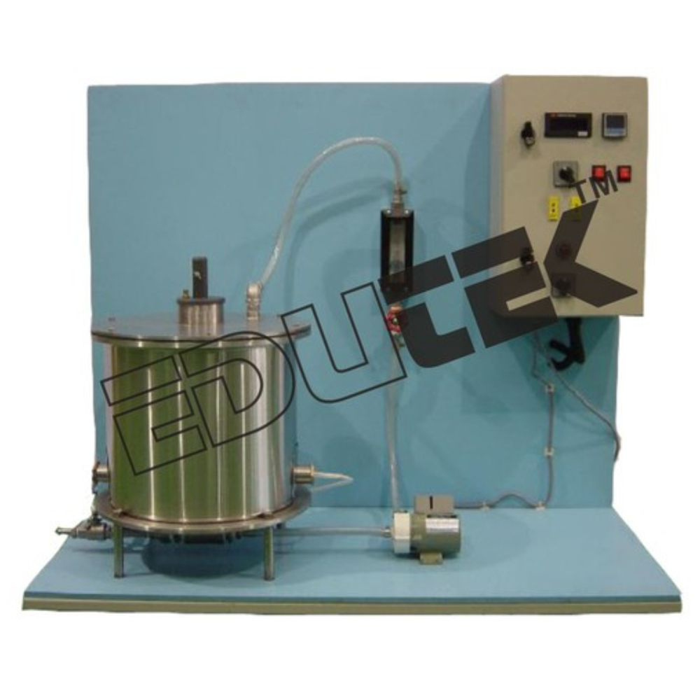
The set up consists of a glass columnpartially filled with sand.
A heater in the form of cylinder isplaced in the bed to heat the sand.
Compressed air supply from end userin laboratory will be provided and is fed at the bottom of the column. Flowrate of air is measured using orifice meter and manometer.
The heater input can be controlled bythe Digital Temperature Controller.
Temperature sensors are provided tomeasure the temperature of air inlet and air outlet.
The whole set-up is well designed andarranged on a rigid structure painted with industrial PU Paint.
Experimentation/Learning Objective
To calculate heat transfercoefficient of the fluidized bed.
Utilities Required
Electricity Supply: 1 Phase, 220 V AC, 50 Hz, 5-15 Amp.combined socket with earth connection (Earth voltage should be less than 5volts)
Compressed Air Supply: 1 CFM @ 2 Bar, with end connectionfor 6 x 8 mm PU tubing.
Floor area: 1. m x 0.75 m
Efficient Heat Transfer Analysis in Fluidized BedsThis unit is engineered for in-depth analysis and measurement of heat transfer properties in fluidized beds, supporting experimental learning in laboratory settings. With a transparent structure and precise instrumentation, students can visualize and evaluate heat transfer efficiencies, leveraging accurate air flow and temperature control. The robust build ensures durability and ease of use, making it a reliable choice for both instruction and research.
Simple Operation and Accurate MeasurementsDesigned for user convenience, the unit features a digital temperature controller and built-in sensors to provide real-time data on air temperatures. The compressed air flow can be easily monitored using the integrated orifice meter and manometer, offering consistent and reproducible results for experiments.
FAQ's of FLUIDIZED BED HEAT TRANSFER UNIT:
Q: How is the Fluidized Bed Heat Transfer Unit set up and operated in the laboratory?
A: The unit is installed on a dedicated floor space of 1 m x 0.75 m. Connect the device to a single-phase 220V AC electrical supply, ensuring earth voltage is below 5 volts. The glass column is partially filled with sand, and compressed air from the laboratory source is connected to the base. The heater is controlled by the digital temperature controller, and sensors measure temperature at key points. Air flow is tracked via the orifice meter and manometer.
Q: What is the primary usage of this heat transfer unit?
A: The main use of this unit is for laboratory experiments focused on determining the heat transfer coefficient in fluidized beds. It supports both academic instruction and research, helping users understand and analyze heat transfer phenomena in granular materials under fluidization.
Q: When should the compressed air be supplied to the unit during experiments?
A: Compressed air should be supplied before starting the heater to ensure an even distribution of sand particles within the column. Proper airflow fluidizes the sand, making the heat transfer experiment effective and the data obtained reliable.
Q: Where should the unit be placed within the laboratory for optimal operation?
A: Place the unit on a stable, level surface with sufficient clearance around its 1 m x 0.75 m footprint. Ensure proximity to electrical outlets and the compressed air supply for safe and efficient operation.
Q: What are the key benefits of using this heat transfer equipment in an educational environment?
A: This unit enables hands-on learning, enhances understanding of fluidized bed dynamics, and provides accurate, real-time data for analysis. Its transparent glass column allows easy observation, while the controlled heating and measurement systems ensure reliable and reproducible results for a range of experiments.
Q: How does the process of calculating the heat transfer coefficient work with this unit?
A: First, set up the heater and ensure the sand is fluidized by introducing compressed air. Adjust the heater and record temperature readings at air inlet and outlet points. Measure the air flow using the built-in orifice meter and manometer. Analyze the collected data to compute the heat transfer coefficient according to standard heat transfer equations.




 Send Inquiry

 Send Inquiry


